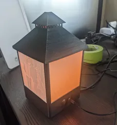
Lithophane Photo Lantern
Published on: Apr 24, 2022
Let your smile light up a room, even when not there.
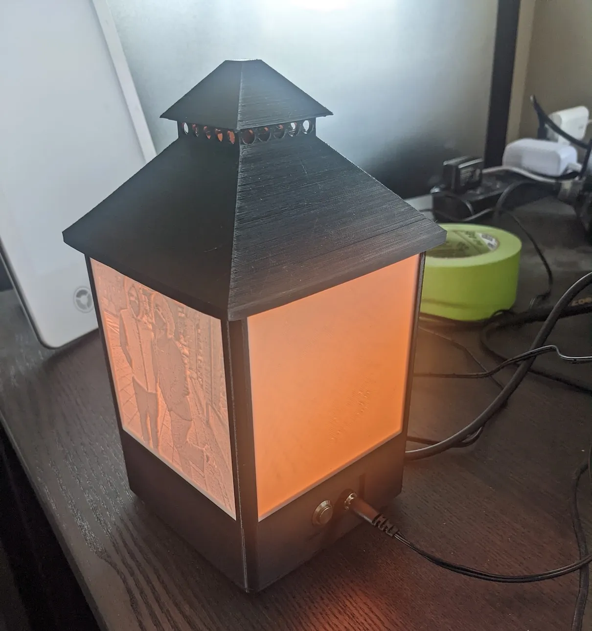
I designed and built this photo lantern. Each side holds a removable 100x100mm lithophane (3D printed photo), illuminated by LEDs controlled over Wi-Fi.
Enclosure
The printed enclosure is divided into three main parts:
- The base holds the circuit board and includes the rails that support the lithophanes.
- The internal insert supports the central LED post and covers the electronics.
- The removable lid closes the lantern and allows the lithophanes to be replaced.
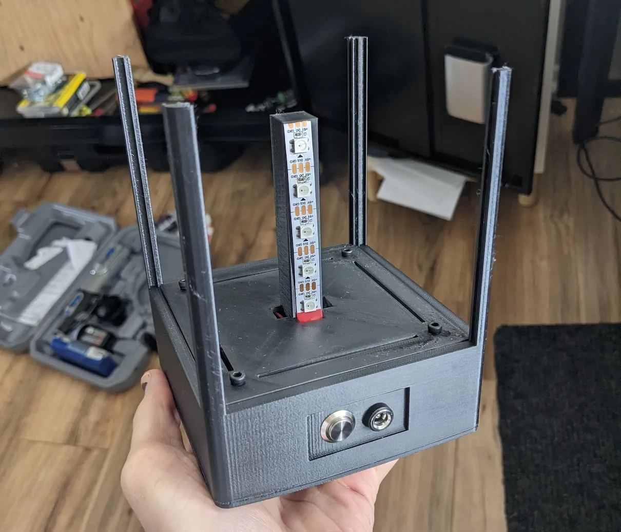
Separating the base and insert simplified assembly. The LED structure could be built and wired independently, then connected to the circuit board before the two sections were fastened together. The top lid uses a friction fit rather than screws because it needs to be removed whenever the images are changed.
I printed the structural parts in PETG. Its greater heat resistance reduced the risk of the center post deforming around the LEDs. Its toughness and slight flexibility were also needed around the corner posts, which are the weakest parts of the frame. The base and internal insert are assembled using screws and heat-set threaded inserts. The circuit board is mounted the same way. Because this was a hand-built prototype, I wanted to be able to reopen it to repair a solder joint, correct a loose connection, or modify the electronics. The inserts provide a more durable connection than repeatedly threading screws directly into the plastic.
Ventilation openings in the electronics cover and the top of the lantern create a partial bottom-to-top airflow path.
Future Improvements
The design does not have a dedicated intake opening at the bottom, so the airflow path is not ideal. Given the small number of LEDs, the low power consumption of the ESP8266, and the 75% brightness limit, I did not expect heat buildup to become significant. A revised enclosure would add a clearer lower intake path.
Electronics
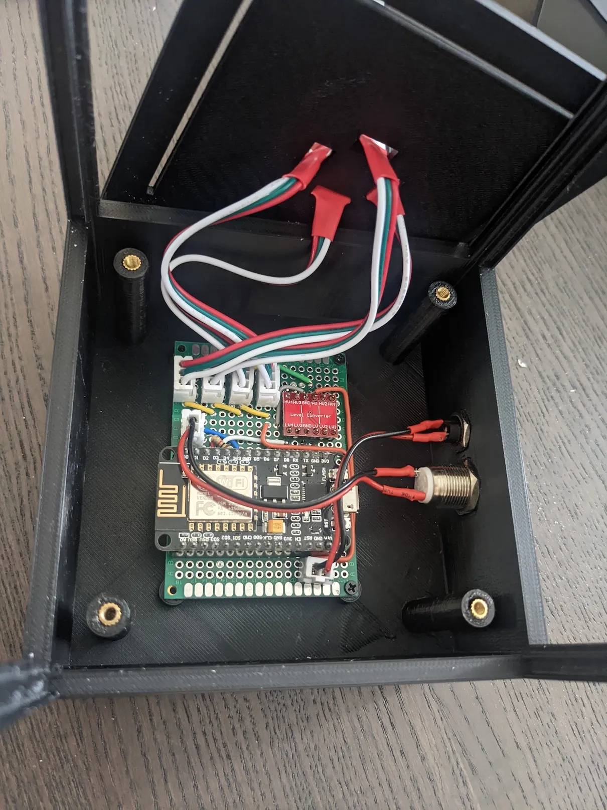
The lantern is controlled by an ESP8266 running the WLED firmware. WLED is a project that provides a web interface for controlling the lights, a captive portal for initial setup, brightness limited fucntionality, and support for physical buttons.
The light source consists of 20 WS2812B addressable LEDs. WS2812B LEDs use 5 V power and are designed for a 5 V data signal. Although Reddit claims they can often accept the ESP8266’s 3.3 V output, I added a logic-level converter to avoid using an out-of-spec signal.
A recessed button on the back provides a simple way to turn the lantern on and off.
Power Usage
At full white and maximum brightness, each LED can draw approximately 60 mA. For 20 LEDs, that gives a worst-case LED load of 1.2 A. The ESP8266 itself typically draws much less (80mA avg), but its Wi-Fi radio can produce higher current peaks (~120mA using 802.11n). I allowed approximately 400 mA total for the development board, including voltage-conversion losses, indicator LEDs, and other onboard components. This resulted in a estimate of roughly 1.6 A, so I selected a 5 V, 3 A barrel-plug supply to be safe.
I also limited the maximum brightness to 75%, the lantern does not need its full output to illuminate the lithophanes.
Future Improvements
The giant, obvious, serious weakness in the current design is the power input. Barrel connectors do not guarantee a consistent voltage or polarity, so connecting the wrong adapter could damage the LEDs or controller. A future version would use USB-C power delivery instead.